今天小编要和大家分享的是circuit相关信息,接下来我将从Single-inductor circuit genera,high technology pcb assembly circuit board pcba这几个方面来介绍。

circuit相关技术文章Single-inductor circuit genera
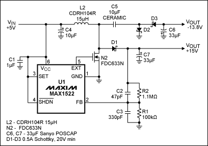
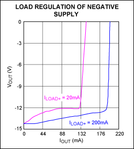
The single inductor and three Schottky diodes associated with this step-up converter derive +15V and -14V from a +5V source. The +15V output delivers as much as 200mA, with efficiencies up to 85% and about 44mV of output ripple. A similar version of this article appeared in the October 6, 2008 issue of EE Times magazine.Many circuit techniques can generate bipolar supply voltages from a single positive voltage, but most of them require multiple inductors. In Figure 1, a single inductor and three Schottky diodes derive +15V/-14V from a +5V source while reducing the circuit size and minimizing cost. The circuit is capable of meeting the demands of most analog circuitry, including audio, instrumentation, and industrial applications. It provides output currents up to 200mA with low output ripple (100mVP-P), and drives several amplifiers drawing 5mA to 10mA each. Figure 1. This single-inductor, 200mA power supply derives +15V/-14V from +5V.A voltage-mode, step-up switching converter (U1, MAX1522) requiring no expensive current-sense resistors generates the +15V output using a fixed on time and minimum off time. The negative rail is generated by an external charge pump consisting of D2, D3, C5, and C6. Because the negative rail is not regulated, it is not as stable as the positive rail, and varies with current drawn from the positive supply (Figure 2). Note also, that U1’s latched-fault mode shuts down the controller in response to a short circuit.
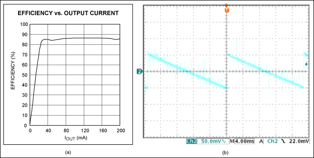
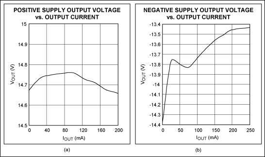
 Figure 2. Load regulation for the -14V output in Figure 1 depends on load current drawn from the +15V output (curves shown are for 20mA and 200mA drawn from +15V).The +15V output delivers as much as 200mA, with efficiencies up to 85% and about 44mV of output ripple (Figure 3). Load regulation for both outputs is shown in Figure 4. As for all switching converters, a good printed circuit board layout is essential for low-noise operation.
 Figure 3. Output efficiency (a) and ripple (b) are as shown for the +15V output in Figure 1, loaded with 200mA.
 Figure 4. These curves from Figure 1 show the output regulation for +15V, with 200mA load on -14V (a), and the output regulation for -14V, with 200mA load on +15V (b).
关于circuit就介绍完了,您有什么想法可以联系小编。